How to tune a damper

Ask most people how a damper is tuned and they will picture an engineer at a test track, adjusting something until the car feels right. That moment is real, and it is still where sign-off happens. But by the time the car turns a wheel, most of the decisions have already been made. Marcin Knapczyk, Chief Engineer at BWI Group, explains the process of damper tuning.

Where does tuning actually begin?

A long way from the car. It all starts with the customer and what they want to achieve. We normally work to a statement of requirements the size of a small book. It defines what the product needs to do and therefore what needs to be tested: durability requirements, hot and cold temperature ranges, all the different conditions the vehicle will meet in its life. Alongside that sits the performance target.

So the requirements are set. How does the system get into the vehicle?

Every project starts with integrating the system into the customer’s architecture. For semi-active system like MagneRide, that means aligning our software with their control environment and making sure everything communicates properly. Only once the system is operational do we begin calibration, adjusting control parameters to match the ride and handling characteristics the customer is after.

We have become more modular about how that works. We can supply a complete MagneRide system, including the dampers, sensors, ECUs and software, or just the individual components required. Some customers want full system delivery and tuning support. Others prefer to embed our control algorithms into their own ECUs.

Once you are up and running, what are you actually looking for?

We refine the system through real-world testing, evaluating ride comfort, body control, noise and vibration levels and overall vehicle dynamics, and we work towards whatever the customer wants the car to be, whether that is sharp handling for a performance model or a more composed ride in an electric SUV.

Underneath those targets are two things we have to control at once. Primary ride is body movement. Secondary ride is wheel control. MagneRide can respond in just a few milliseconds, which allows us to control both precisely. On a challenging surface such as an uneven country road, that responsiveness makes a real difference: we can maintain strong body control without introducing harshness from the wheels. Other systems often reach a point where they have to increase damping to control the body, and that leads to an overly stiff ride.

When the driver comes back with feedback, how quickly can you act on it?

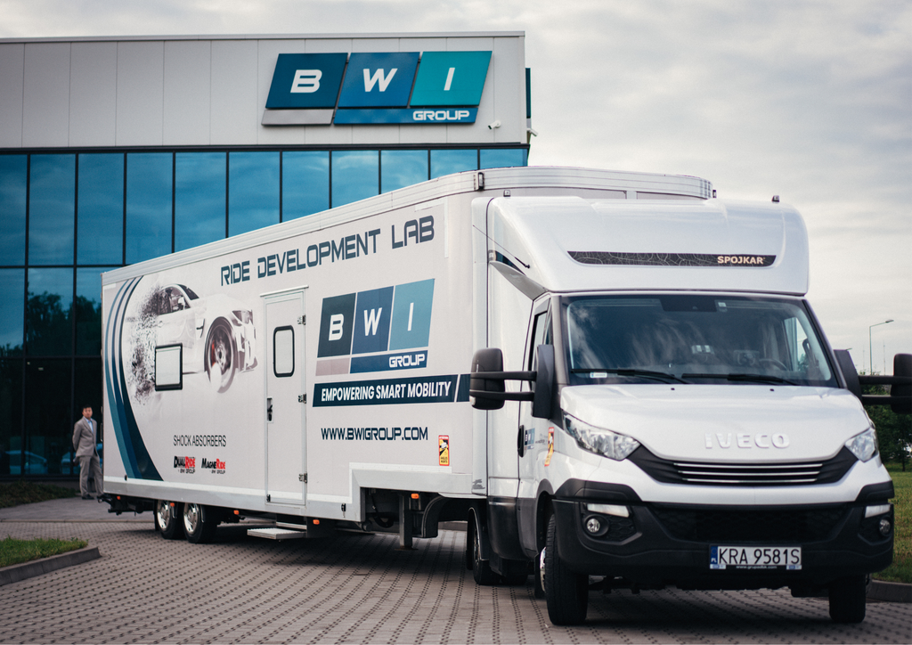
That is what magnetorheological damping changed. Traditional passive systems use valves, which often require physical hardware changes during development. You are manufacturing and swapping out multiple sets of valves to refine the tuning, and that is time-consuming and resource-intensive. Ride Van, our mobile laboratory, travels and resides at a customer’s site (proving ground) where physical changes are made

With MagneRide we do not need to change any hardware during tuning. The damping force is controlled digitally through software, so our ride engineers can make changes directly from a laptop. That gives us much more agility in development, reduces cost and speeds up the entire calibration process.
How much of the final judgement is still subjective?

Subjective evaluation is a critical part of sign-off, and it is not going away. The complexity of modern vehicles, with all the subsystems in a modern chassis, makes it extremely difficult to do everything virtually, and an expert driver can evaluate the car across many conditions in a very short time. In subjective evaluation your body is the sensor, and you cannot simulate that. Even with all the AI we have now, it is difficult to describe what we are looking for.

How do you know when a tune is finished?

The bench test verifies durability and, in a more limited way, performance. The vehicle is where we verify that performance and define the nominal damper that is then reproduced in series production. After the ride session we have a master set, which is the evidence of what the customer tested.

How is simulation changing the shape of all this?

One of the biggest impacts is the reduction in the number of physical prototypes. One OEM told us they can now build ten times fewer test vehicles for a new vehicle generation than before, and a prototype car is extraordinarily expensive. The downside is that there is less access to prototype vehicles, which in turn encourages more virtual testing. It follows through to us as well: fewer prototype vehicles mean fewer prototype dampers to produce. Where simulation helps us most is FEA and CFD, predicting failures and avoiding them, which reduces the number of samples required.

So where does damper development go next?

It will continue to move towards bench testing. Using hardware in the loop to extend virtual testing and validate your models is much more cost effective and quicker than track testing, and you want the product to be as mature as possible before progressing to in-vehicle testing. But there will always be a need for physical vehicle dynamics testing.

The other direction is software. As EV adoption increases, expectations around noise and ride quality rise with it. Without engine noise to mask imperfections, every bump and vibration becomes more noticeable, and the added mass of an EV makes controlling body motion more challenging. At the same time the shift towards software-defined vehicles is accelerating the need for digitally controlled suspension that can be integrated and updated easily.

BWI Group opens Brazil R&D Centre

BWI Group has begun operations at a new R&D centre in the São Paulo region, giving automakers in South America dedicated local technology support for brake-by-wire, stability control and foundation brake programs.

BWI Group, a global leader in chassis technologies, has begun operations at its new Brazil R&D Centre. The facility will provide dedicated local technology support for the South American market and further extends BWI Group’s global R&D network, which now covers China, Europe, North America and South America.

Brazil is on course for more than three million vehicle sales in 2026, an increase of 12.1% on last year[RD1] , and a rising import tariff has pushed a wave of new vehicle assembly into the country. Local engineering support has become part of what automakers expect from their chassis suppliers in the region.

A local base for South American programs

Located in the São Paulo region, the BWI Group Brazil R&D Centre focuses on brake-by-wire technology, with activities covering product R&D, platform localization and technical support. Together with BWI Group’s two R&D centres and one manufacturing plant in North America, it helps automakers roll out their programs across South America.

Bringing brake-by-wire technology to the region

BWI Group has brought the 9th generation of its Electronic Stability Control (ESC) system into mass production at multiple sites worldwide, and the system will be introduced in South America for the first time this year.

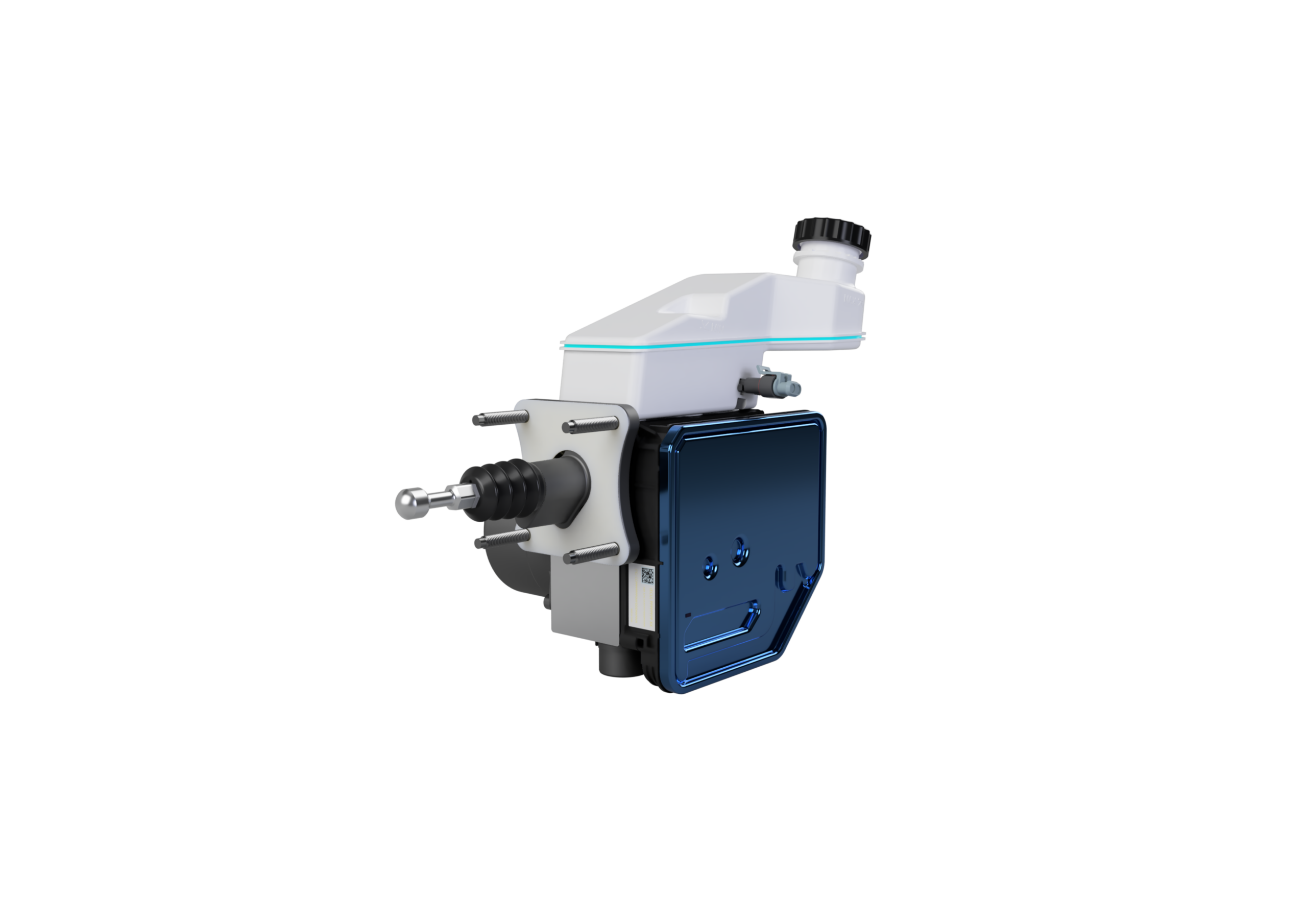
The iDBC1 integrated brake-by-wire (1-Box) system will also be added to the South American brake-by-wire roadmap. The 1-Box system entered mass production in China in 2025 and has recently ramped up to mass production in Europe. The international expansion of the foundation brake business covers integrated Electric Parking Brake (EPB) systems and callipers.

Supporting automakers as they expand

Advanced suspension and brake technologies remain the foundation of BWI Group’s support for its automaker customers. As a Tier 1 chassis technology supplier with a long-established global presence, BWI Group will combine localised technical support with its wider service capabilities to work closely with automakers as they grow in global markets.

BWI Group is the only Chinese supplier of brake-by-wire products to mainstream European and American automakers. In the automotive suspension sector, BWI Group also holds the top position among Chinese brands in terms of global market share.

Optimising brake pedal feel through software – iDBC (1-BOX)

Battery electric vehicles accounted for 20% of new EU car registrations in the first five months of 2026, up from 15.3% a year earlier, according to ACEA . Add hybrids and plug-in hybrids and more than two thirds of new cars are electrified.

OEMs have a decision to make with electrified vehicles. Use regenerative braking; blending regen with the friction brakes as necessary. Or solely rely on lift-off regen, which is how one-pedal driving became a defining EV behaviour. The first maximises range but typically has poor brake pedal feel, the other has an unaffected brake pedal but is wasting energy.

The handover is where the driver feels the friction brakes take over from regen part-way through a stop. This is particularly noticeable in the last 10km/h of a stop because the electric motor needs to be rotating to generate torque. There are a multitude of variations that mean making brake pedal feel consistent is a real challenge. For example, when the battery is in a high state of charge full regen is unavailable, so the same pedal input produces a different response compared to when the battery is low. Battery temperature, brake temperatures, brake pedal force – these all impact what blend of regen and friction brake is required.

Decoupling the pedal

Through this approach pedal feel can be calibrated to the character of the vehicle: firm and short for a performance derivative, progressive and light for a luxury saloon, and switchable between drive modes on the same car. Decoupling the brake provides better control of the deceleration whether the stop is served by regen, friction or a blend, and regardless of battery state of charge.

An added benefit of an integrated electronic system is that the motor builds pressure around three times faster than a vacuum booster. Reaching full pressure sooner in an autonomous emergency braking situation at highway speeds has a significant impact on stopping distances.

Optimising range

A coupled system has to bring friction brakes in early because the pedal is mechanically linked. A decoupled system can serve the majority of the stop through regen wherever grip, temperature and battery conditions allow, introducing friction only when demand exceeds what the electric machine can absorb. The driver feels one consistent pedal throughout.

Engineered safety

What happens if the electronics fail on a decoupled brake pedal? Our iDBC was designed around fail-safe operation from the concept stage. The system is developed to ASIL-D and a direct hydraulic path from the pedal pushrod to the calipers remains as a mechanical backup. Even under a fault condition that disables every electronic system on the vehicle, the driver can still stop the car.

A brake system needs to be proven durable and safe across the full operating envelope, which is why the iDBC has been through high and low temperature programmes and a full winter test cycle on ice and snow at our low-adherence facility in Arjeplog, northern Sweden.

Pedal feel in the EV era

The nuances of subjective driving characteristics, such as pedal feel, steering weight and damper tuning, can be key brand differentiators, but noticed, in truth, mainly by enthusiasts and the engineers who created them.

Brake pedal feel in the EV era is different. Poor blending is not a nuance and it is immediately obvious to all drivers, whether they can name it or not. It erodes confidence in the car, and confidence is harder to rebuild than it is to lose.

The ambition, then, is not necessarily a pedal feel that impresses. It is a pedal the driver never thinks about. That is a higher bar than it sounds and it is easier to achieve when the pedal is decoupled and software controlled.

Compressing development from weeks to an hour

BWI Group’s Technical Centre Krakow has developed a bespoke artificial intelligence (AI) FEA tool. In a recent demonstration project it cut air spring development time from weeks to roughly one hour and uncovered a viable design that experienced engineers had already ruled out. We sat down with Miroslaw Siemieniuk, FEA Manager at BWI Group, to find out how it works, what it found, and why he believes the engineer’s role becomes more important, not less.

Mirosław Siemieniuk, FEA Manager at BWI Group

Q: Miroslaw, let’s start with the wider picture. Why have you and the team developed this AI-powered FEA tool?

A: That’s agood question. The automotive industry has changed rapidly over the last 10 years or so. Due to safety and electrification vehicles continue to increase in mass and at the same time development timescales are reducing. This is having a significant impact on chassis engineers, who are now being asked to land on tighter performance targets inside narrower programme windows.

Air suspension is a good example of where these pressures are being felt. Ride, handling, comfort and durability are governed by a large set of design variables that interact in tightly coupled, non-linear ways and resolving them is challenging. So there was a clear opportunity here to benefit from the potential AI has to offer.

Q: Walk us through how an air spring is typically developed today. Where does the bottleneck sit?

A: Typically, the starting point is a force-versus-displacement performance curve supplied by the OEM. This defines exactly what the air spring is required to deliver across its full stroke. Our aim is to try and develop a product that matches that curve as closely as possible.

However, due to the many linked interactions of the various components in an air suspension system, hitting that curve and satisfying a number of other conflicting requirements and constraints is rarely straightforward. Internal geometry, working pressure, sleeve material behaviour and reinforcement layout all influence the result. The current approach is iterative manual design, with each step supported by finite element analysis (FEA). For a capable team, converging on a workable design typically takes several weeks.

Q: How does the new AI-powered FEA tool change that?

A: In short,it replaces the repeated manual iteration with a deep-learning surrogate that evaluates design changes almost instantly. This is why Ai in engineering can excel. On the particular air spring used in this study, the full optimisation completed in approximately one hour. So, compared to a typical two-week baseline, that is a 98 percent reduction in process time.

Q: How is the deep-learning model built?

A: The surrogate is a five-layer deep neural network. Importantly, it has been trained on a set of 180 high-quality FEA datasets. Those datasets came from simulation models that had already been correlated against extensive laboratory testing. So we know the models have been physically verified and the network is learning from solid engineering data.

From that training set, the network learns the mapping between the air spring’s design parameters and its resulting force-displacement behaviour and is then used as a fast-evaluating surrogate for the underlying FEA. As with all simulation processes, accuracy and correlation are critical. Against the simulation reference, the model achieved an R-squared of 0.99. In other words, there is strong agreement between its predictions and full FEA outputs.

Q: What design parameters does the model currently optimise?

A: At present, the neural network is wrapped around five design parameters: piston radius, low support radius, sleeve thickness, design pressure and nylon fibre cord angles. A Newton-based optimisation algorithm drives the search, looking for the combination of those parameters that minimises the residual error between the surrogate’s predicted force-displacement curve and the OEM’s target. The resulting root mean square error came in at approximately two percent, which indicates that the expected system behaviour closely matches the target. Once an optimal configuration is identified, the candidate design is subjected to a final detailed FEA for validation.

Q: Did the model uncover anything that was unexpected?

A: It certainly did. During the manual phase of the project, the team had concluded that the target force-displacement curve could not be matched within the existing architecture without adding a specific structural constraint component.

However, the AI tool had a different answer. It identified a combination of parameters that met the target curve inside the defined parameter space without the additional component. Manual iteration had not highlighted it because the number of interacting variables put it outside what could realistically be searched by hand inside any reasonable programme timeline.

It is important to emphasise that this is a demonstration of feasibility. The project has not been signed off for production. Translating it into hardware would still require full testing and validation. But, I think it clearly demonstrates the value of AI in surfacing non-intuitive solutions.

Q: If this approach were ultimately validated for production, what would the implications be for OEMs?

A: The implications of developing a design that does not require this additional structural component are significant. Removing it would lower mass, reduce cost, simplify the assembly process and remove the tooling associated with that hardware. More generally, the workflow gives engineering teams a clearer view of where the limits of a given suspension architecture actually sit.

Q: What does this mean for the engineer’s role in suspension development?

A: At BWI Group, AI is treated as an extension of our engineering practice. Its effectiveness depends heavily on engineering judgement. You can have the best tool in the world, but if you don’t know how to use it then it has little value. The quality of the FEA training data, the assumptions baked into each simulation model and the choice of which parameters to expose to the network all need experienced hands and understanding.

Building and validating the simulation models that produce the training data is itself a substantial engineering exercise. If the model is fed bad data, you will only get bad results. Without a credible physical foundation underneath it, the AI model’s outputs lose meaning quickly. What changes for the engineer is where they can now focus their efforts. Repetitive iteration is what gets automated, so the work can instead shift towards innovation.

Q: Where does the methodology go from here?

A: The five-parameter version described here is just the first version. There is clear scope for growth and future iterations will add more design variables, such as sleeve height, piston geometry and air spring volume. The methodology itself is not specific to air springs. So the same approach is now being applied to other suspension sub-systems, including passive valve set ups.

Q: Final thought. What is the broader lesson from the project?

A: A properly grounded surrogate model can do two things at once: compress the development timeline by orders of magnitude, and reveal design solutions that engineers simply do not have time to find. The engineering fundamentals come first, and the AI amplifies what our teams can achieve with them.

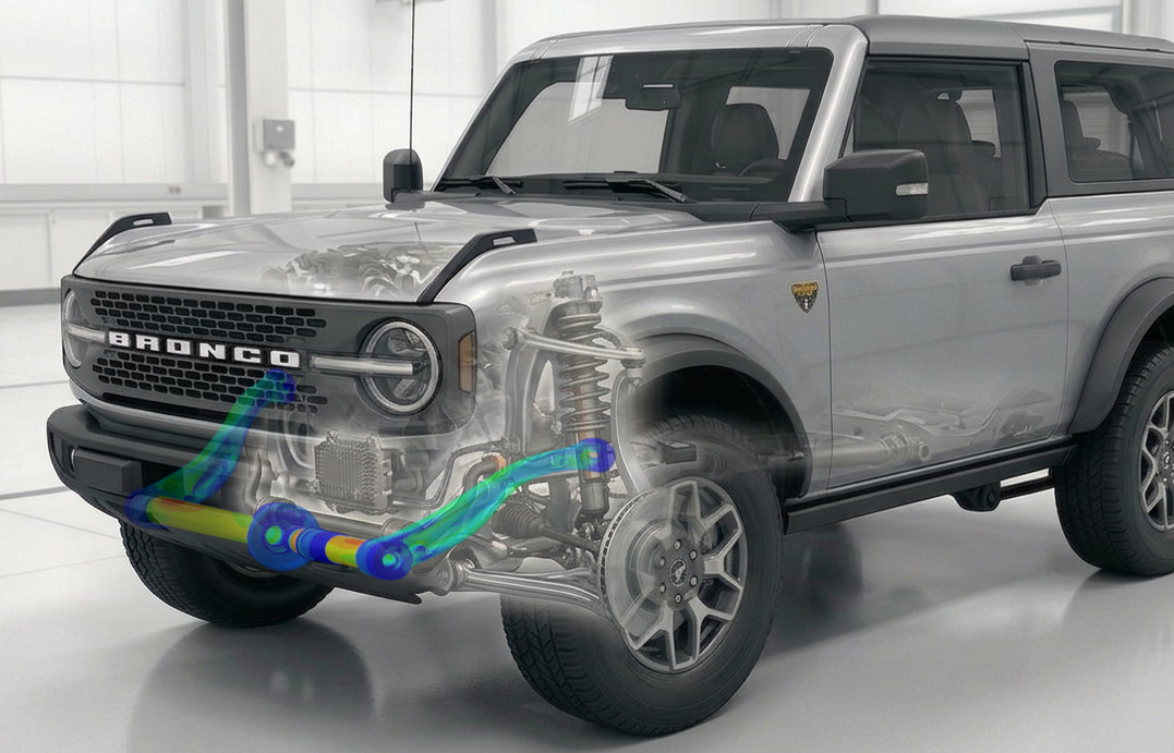
Semi Active Roll Control System (SARC) with a new automatic mode 

  • Automated roll control system can be connected and disconnected on demand while driving at speed

  • SARC removes the compromise between handling and comfort while also improving off-road capabilities

  • Its unique hydraulic architecture enables mode transitions at any suspension travel and even under load

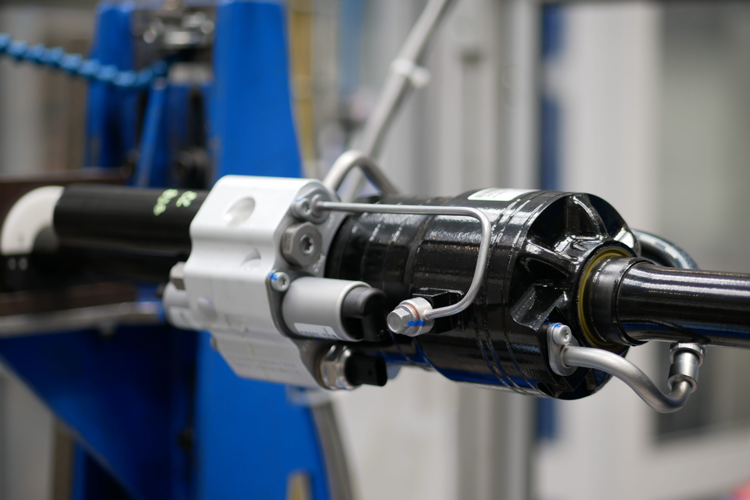
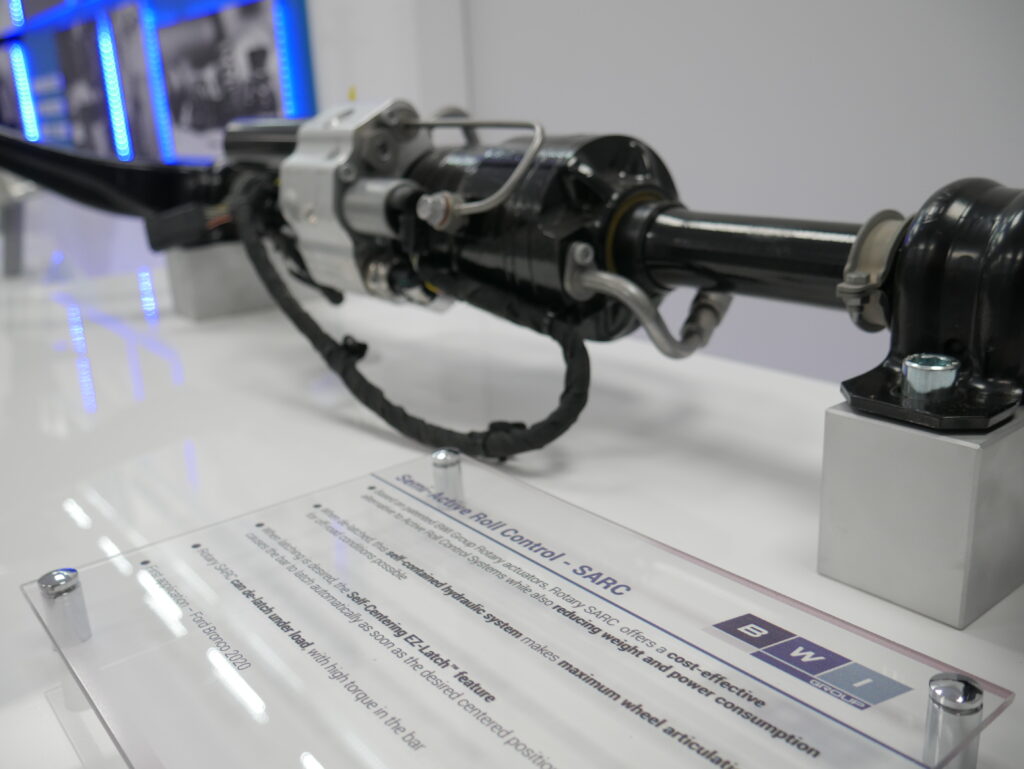
BWI Group has developed an automated active roll control system. The latest update to the company’s SARC (Semi Active Roll Control) product features a new ‘automatic mode’ that enables a vehicle’s anti-roll bar to disconnect and reconnect seamlessly on demand while driving at speed.

The update addresses an increasing challenge in modern chassis engineering as vehicle mass continues to grow. With SUVs accounting for more than half of new car registrations in Europe in 2024, and BEVs typically around 30% heavier than equivalent ICE models, engineers are increasingly forced to compromise between roll stiffness for handling and compliance for comfort. Heavier vehicles necessitate stiffer stabiliser bars, which extenuates the issue.

SARC’s automatic mode aims to remove this compromise. By disconnecting the bar during normal driving, the system allows the vehicle to adopt a softer, more compliant baseline, only engaging the stabiliser bar when required. The control unit uses vehicle data, such as steering angle, speed, lateral acceleration and yaw rate, to determine when the bar needs to reconnect. During high-speed cornering, for example, it reconnects in less than 200 milliseconds and is imperceptible to the driver.

“Chassis engineers are continually trying to improve road handling and comfort, but the two goals are often incompatible,” said Bruno Perree, Engineering Manager at BWI Group. “The latest update to SARC removes that compromise, allowing engineers to optimise the roll bar purely for handling as it will be disconnected the majority of the time. This not only improves comfort but also adds significant off-road capability, which can be a key competitive differentiator in a crowded SUV market.”

At the core of the system is a compact rotary actuator paired with a fully self-contained hydraulic mechanism. The hydraulic architecture enables the bar to be connected or disconnected even when the wheels are unevenly articulated, which is something mechanical solutions typically cannot achieve. Automatic self-centring using the company’s EZ-Latch™ technology ensures consistent engagement throughout the suspension travel.

SARC is in production on several global platforms, most recently the GWM Tank series, where it is used to balance on-road composure with off-road traction. The addition of SARC’s automatic mode is expected to broaden its application to a wider range of SUVs and BEVs, where managing mass and maintaining ride quality have become central engineering priorities.